|
Important Disclaimer: You are solely responsible for any damages, problems, or injuries resulting from opening up and working on your equipment. Unless otherwise indicated, the equipment should be powered off and unplugged while these procedures are being done; otherwise, you can be exposed to potentially fatal voltages. If you do not feel comfortable or competent in performing these tasks, we strongly recommend taking your equipment to a qualified service center. Limitation of Remedies: Syntaur Productions is not liable for any direct, indirect, consequential or incidental damages arising out of the use or inability to use this product. Some states do not allow the exclusion or limitation of liability for consequential or incidental damages, so the above limitations may not apply. |
||||||
|
The #2317 power transformer can be used in several different keyboards, and can be used with any of the standard mains voltages throughout the world. You will need to hook up certain wires on this transformer to configure it for the mains voltage where your keyboard will be used; other wires will be left unused.
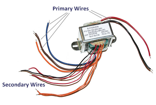
On the primary (input) side of the transformer (the wires that connect to the bottom side of the transformer), the thicker black wire is common, and you should hook up one other wire, depending on the mains voltage where you live:
For 100V input (Japan), use the thicker red wire.
|
||||||
|
After the primary wires are connected, you can connect the secondary wires (the wires from the top side of the transformer) in exactly the same configuration as the original transformer wires (one orange pair, and one red pair with a black wire). You can power on (be careful where you touch!), and test with a voltmeter to make sure you are getting correct voltages at these secondaries. The orange wires should show 9.5 VAC between them, and you should see 19 VAC between either red wire and the black wire, and 38 VAC between the two red wires.
Once you have verified that all voltages are correct, you can snip off the unused primary wires if you like, to keep them out of the way. There is no voltage to these wires, but you don't want the uninsulated ends to inadvertently touch anything they shouldn't.
|
||
|
JX-3P and JX-8P notes: For installation in a Roland JX-3P or JX-8P synthesizer, this transformer must be oriented 180 degrees from the original in order for the wires to reach. In other words, you should install it with the secondary (smaller) wires pointing the opposite direction from the original transformer.
|
||
|
Juno-60 notes: The Roland Juno-60 is originally configured so that moving a soldered jumper on the fuse board can reconfigure it for use with different mains voltages. To maintain this setup, connect the new transformer as follows:
The black primary wire connects to lug 7 of the fuse board, where the original white wire connected. If you like, you can connect only the two wires needed for your mains voltage to the fuse board, and snip off the others. For example, for use in the US, connect just the black and blue primary wires.
|