| Installing Syntaur's Arp Odyssey Sub-Oscillator Kit | ||
|
Important Disclaimer: You are solely responsible for any damages, problems, or injuries resulting from opening up and working on your equipment. Unless otherwise indicated, the equipment should be powered off and unplugged while these procedures are being done; otherwise, you can be exposed to potentially fatal voltages. If you do not feel comfortable or competent in performing these tasks, we strongly recommend taking your equipment to a qualified service center. Limitation of Remedies: Syntaur Productions is not liable for any direct, indirect, consequential or incidental damages arising out of the use or inability to use this product. Some states do not allow the exclusion or limitation of liability for consequential or incidental damages, so the above limitations may not apply. |
||
|
Tools needed: Phillips-head screwdriver 1/2-inch nut driver Drill with 1/8-inch and 9/32-inch bits Soldering iron and solder The wiring from the sub-oscillator board is color-coded as follows: Red: 15-volt input to sub-oscillator board Green: Ground Brown: Signal from Osc 1 Purple: Signal from Osc 2 Black: Output from sub-oscillators |
|
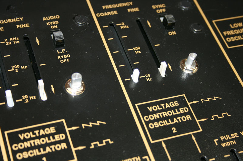
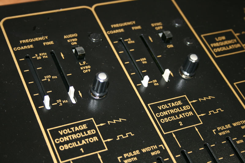
1. Remove slider caps from both VCO sections, and the LFO and S/H section. You may want to take a photo of the unit first, to get the colored caps back in their original configuration once you are putting everything back together.
2. With the synthesizer unplugged, remove all of the screws that go through the plastic tray that forms the bottom and sides of the synth. These consist of three screws on each side, four screws on the bottom panel, and four rubber feet with screws on the bottom panel. 3. With these screws removed, the entire synthesizer and keybed will come free from the plastic tray. You can now lay the synth face-down on a padded work surface, with the keys facing you, and set the plastic tray aside.
|
|
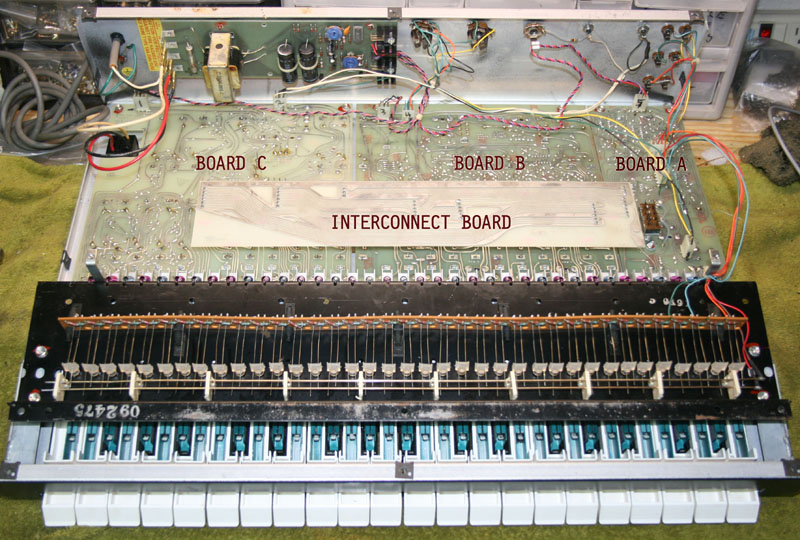
4. It is a good idea at this point to mark the wiring connectors and the circuit board they plug into with a Sharpie, to avoid any confusion as to what wiring plugs where, and in what direction the connector should be. A reference photo of the inside of the unit can be helpful as well. There are three circuit boards secured to the top panel. From left to right, they are Board C, Board B, and Board A, and the Interconnect Board connects the three together.
|
|
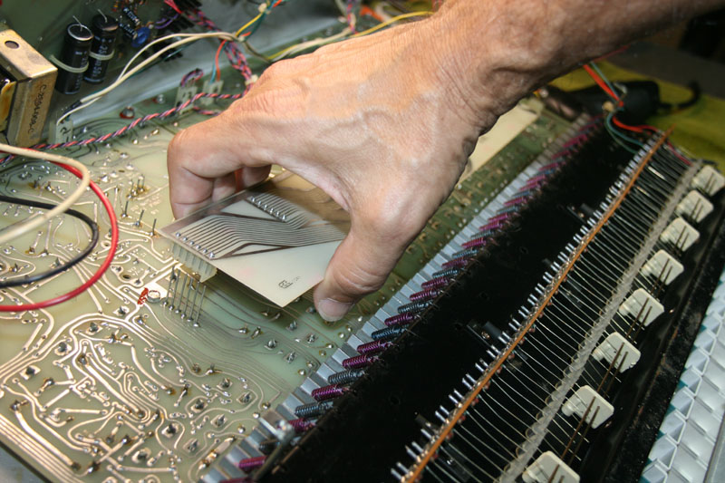
5. Remove the Interconnect Board (see photo above), by pulling it upward, away from the circuit boards underneath it. It will simply slide up and off of the connector pins. |
|
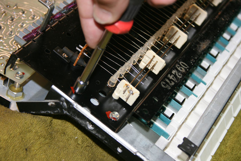
6. Remove the keybed, first by unplugging the wiring connector that runs to Board A, then by removing the four screws that secure the keybed (two on each end) with a �-inch nut driver. Set the keybed aside, being careful not to bend any of the J-wires underneath each key.
|
|
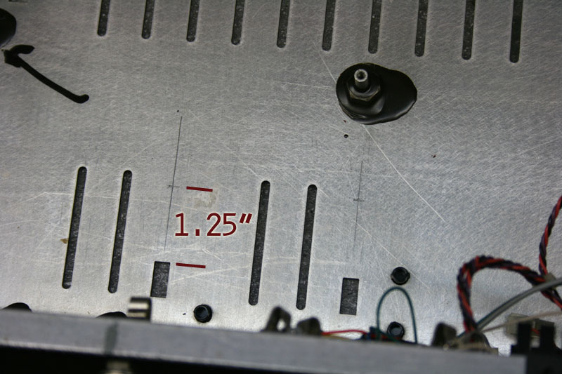
8. On the inside of the metal panel, mark the position of the holes to be drilled for the potentiometers. Use the two rectangular slide switch holes (the Audio and Sync switches) at the top of each VCO section for reference. With a sharp pencil, first draw a line extending from the center of each of these holes, as pictured. Then, place a cross mark on each of these lines 1.25 inch from the edge of the slide switch hole.
|
|
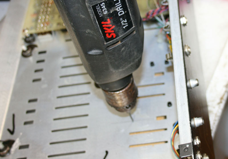
9. Drill a pilot hole at each cross mark with an 1/8-inch drill bit. Be careful to keep the bit exactly on the cross mark when starting to drill - don't let it 'walk' off target, or your potentiometers will not end up perfectly aligned.
|
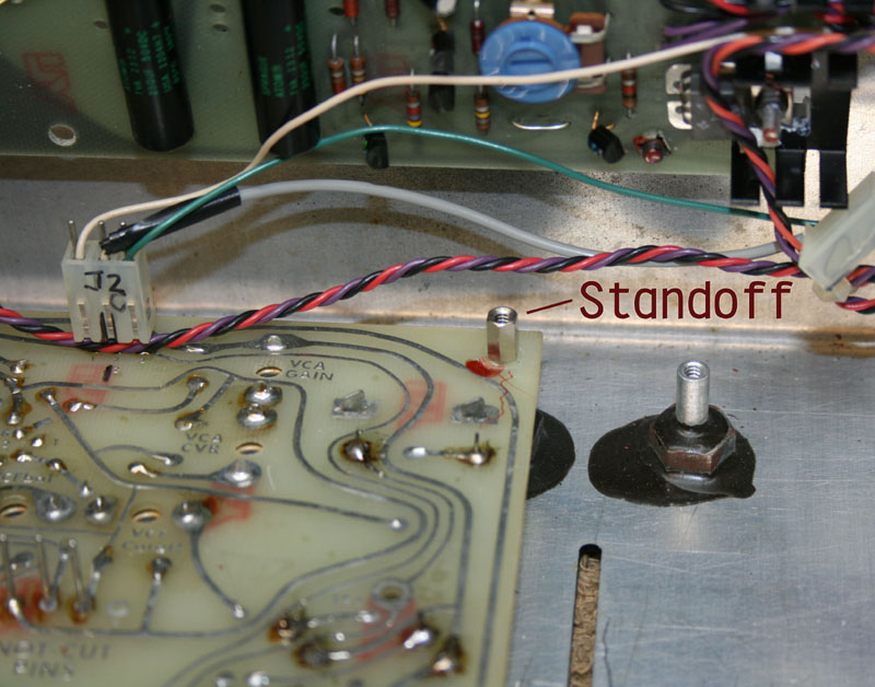
| 11. Remove the mounting screw from the back right corner of Board C, and replace it with the standoff from the kit (see photo above). |
|
12. Mount the potentiometers onto the front panel now. Leave one nut on each potentiometer (screwed all the way down), then position the pot in the hole, and secure the pot with a washer and nut on the top side of the panel. Make sure that the pots are positioned so that the wires point toward the keybed. The pot with the blue, yellow, and green wires goes into the hole for VCO1, the other pot is for VCO2.
|
|
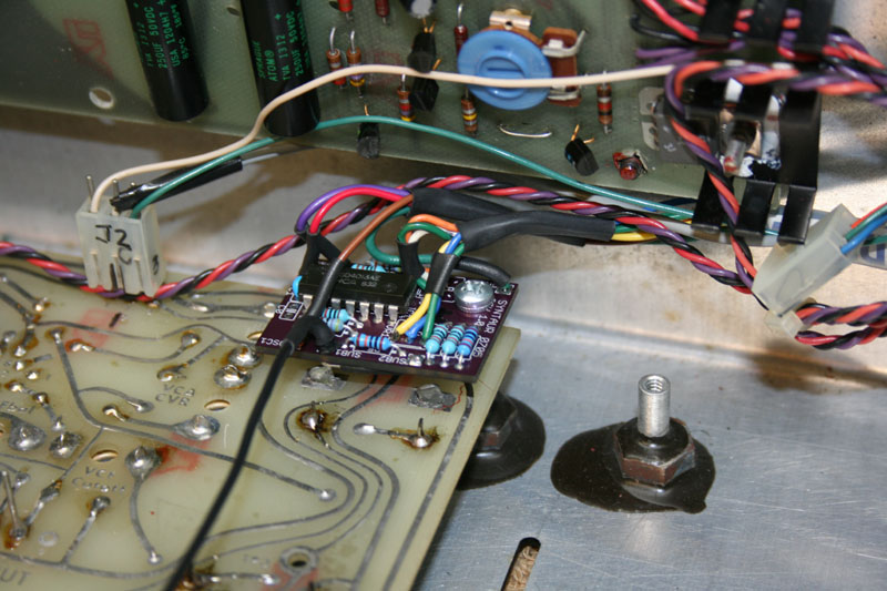
14. With a single screw, mount the sub-oscillator circuit board onto the standoff installed in Board C (from Step 11).
|
|
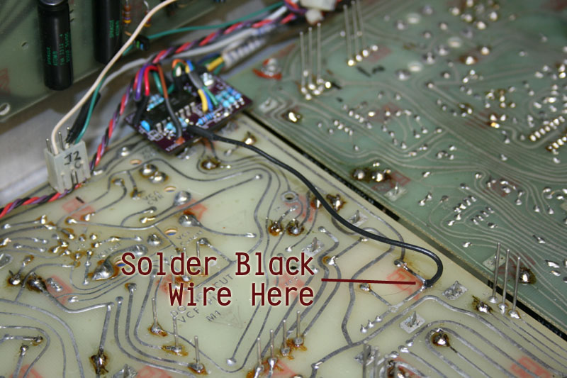
15. Solder the black wire from the sub-oscillator board to Board C as shown above; this is the sub-oscillator output.
|
|
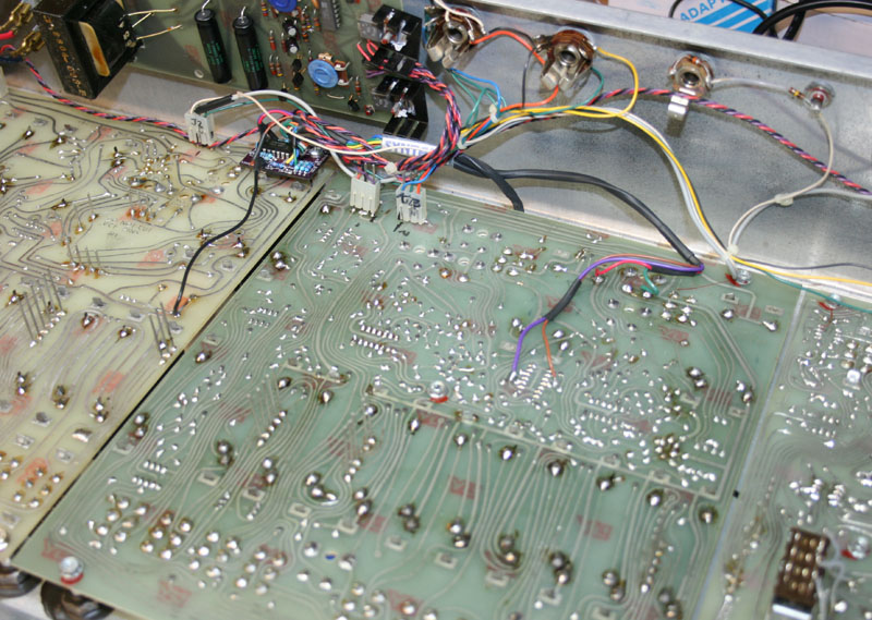
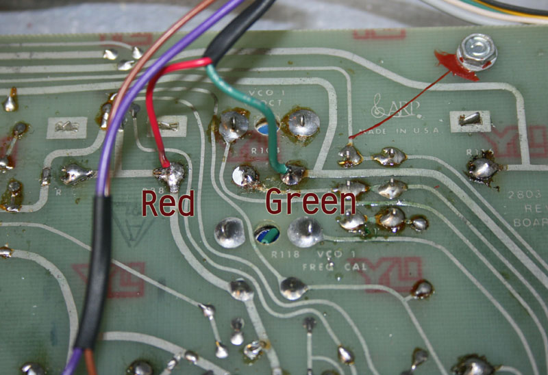
16. The remaining wires attach to Board B as shown. Solder the green ground wire to trim pot R104 on Board B, as shown above and in the next photo.
|
|
17. Solder the red wire (voltage feed to the sub-oscillator board) to R38 on Board B.
|
|
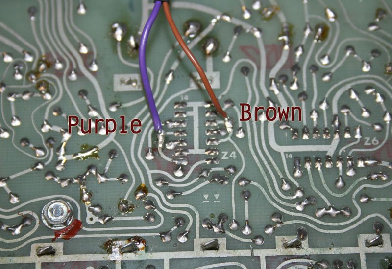
18. Solder the purple and brown wires (oscillator signals to the sub-oscillator board) to the points shown around chip Z4 on Board B. The brown wire connects to pin 3 (which also connects to pin 5), and the purple wire connects to pin 11 (which also connects to pin 8).
|
|
21. Replace the keybed - and don't forget to plug the wiring harness back to Board A!
|